Chapter 4. Routing Concepts
Objectives
Key Terms
Introduction (4.0.1.1)
Functions of a Router (4.1.1)
Characteristics of a Network (4.1.1.1)
Why Routing? (4.1.1.2)
Routers Are Computers (4.1.1.3)
Routers Interconnect Networks (4.1.1.4)
Routers Choose Best Paths (4.1.1.5)
Packet-Forwarding Mechanisms (4.1.1.6)
Process switching
Fast switching
Cisco Express Forwarding
Connect Devices (4.1.2)
Connect to a Network (4.1.2.1)
Default Gateways (4.1.2.2)
Document Network Addressing (4.1.2.3)
Enable IP on a Host (4.1.2.4)
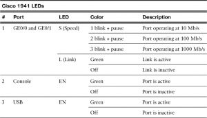
Device LEDs (4.1.2.5)
Console Access (4.1.2.6)
Enable IP on a Switch (4.1.2.7)
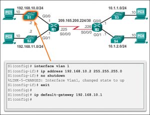
A switch does not have a dedicated interface to which an IP address can be assigned. Instead, the IP address information is configured on a virtual interface called a switched virtual interface (SVI).
Basic Settings on a Router (4.1.3)
Configure Basic Router Settings (4.1.3.1)
Configure an IPv4 Router Interface (4.1.3.2)
Configure an IPv6 Router Interface (4.1.3.3)
Configure an IPv4 Loopback Interface (4.1.3.4)
The loopback interface is a logical interface internal to the router. It is not assigned to a physical port and can therefore never be connected to any other device. It is considered a software interface that is automatically placed in an UP state, as long as the router is functioning.
Verify Connectivity of Directly Connected Networks (4.1.4)
Verify Interface Settings (4.1.4.1)
Verify IPv6 Interface Settings (4.1.4.2)
Filter Show Command Output (4.1.4.3)
Command History Feature (4.1.4.4)
Switching Packets Between Networks (4.2.1)
Router Switching Function (4.2.1.1)
Send a Packet (4.2.1.2)
Forward to the Next Hop (4.2.1.3)
Packet Routing (4.2.1.4)
Reach the Destination (4.2.1.5)
Path Determination (4.2.2)
Routing Decisions (4.2.2.1)
Best Path (4.2.2.2)
A metric is the quantitative value used to measure the distance to a given network. The best path to a network is the path with the lowest metric.
The following lists some dynamic protocols and the metrics they use:
Routing Information Protocol (RIP) – Hop count
Open Shortest Path First (OSPF) – Cisco’s cost based on cumulative bandwidth from source to destination
Enhanced Interior Gateway Routing Protocol (EIGRP) – Bandwidth, delay, load, reliability
Load Balancing (4.2.2.3)
When a router has two or more paths to a destination with equal cost metrics, then the router forwards the packets using both paths equally. This is called equal cost load balancing.
Note: Only EIGRP supports unequal cost load balancing.
Administrative Distance (4.2.2.4)
RIP chooses a path based on hop count, whereas EIGRP chooses a path based on its composite metric. How does the router know which route to use?
Cisco IOS uses what is known as the administrative distance (AD) to determine the route to install into the IP routing table. The AD represents the “trustworthiness” of the route; the lower the AD, the more trustworthy the route source.
| Route Source | Administrative Distance |
| Connected | 0 |
| Static | 1 |
| EIGRP summary route | 5 |
| External BGP | 20 |
| Internal EIGRP | 90 |
| IGRP | 100 |
| OSPF | 110 |
| IS-IS | 115 |
| RIP | 120 |
| External EIGRP | 170 |
| Internal BGP | 200 |
Analyze the Routing Table (4.3.1)
The Routing Table (4.3.1.1)
Specifically, a routing table is a data file in RAM that is used to store route information about directly connected and remote networks. The routing table contains network or next hop associations. These associations tell a router that a particular destination can be optimally reached by sending the packet to a specific router that represents the next hop on the way to the final destination. The next hop association can also be the outgoing or exit interface to the next destination.
Routing Table Sources (4.3.1.2)
show ip route command can be used to display the IPv4 routing table of a router.
Entries in the routing table can be added as:
Local Route interfaces – Added when an interface is configured and active. This entry is only displayed in IOS 15 or newer for IPv4 routes and all IOS releases for IPv6 routes.
Directly connected interfaces – Added to the routing table when an interface is configured and active.
Static routes – Added when a route is manually configured and the exit interface is active.
Dynamic routing protocol – Added when routing protocols that dynamically learn about the network, such as EIGRP or OSPF, are implemented and networks are identified.
Remote Network Routing Entries (4.3.1.3)
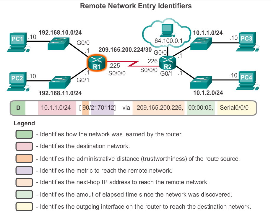
The entry identifies the following information:
Route source – Identifies how the route was learned.
Destination network – Identifies the address of the remote network.
Administrative distance – Identifies the trustworthiness of the route source. Lower values indicate preferred route source.
Metric – Identifies the value assigned to reach the remote network. Lower values indicate preferred routes.
Next-hop – Identifies the IPv4 address of the next router to forward the packet to.
Route timestamp – Identifies how much time has passed since the route was learned.
Outgoing interface – Identifies the exit interface to use to forward a packet toward the final destination.
Directly Connected Routes (4.3.2)
Before the interface state is considered up/up and added to the IPv4 routing table, the interface must:
Be assigned a valid IPv4 or IPv6 address
Be activated with the no shutdown command
Receive a carrier signal from another device (router, switch, host, etc.)
When the interface is up, the network of that interface is added to the routing table as a directly connected network.
Directly Connected Interfaces (4.3.2.1)
The routing table entry for directly connected interfaces is simpler than the entries for remote networks. The entries contain the following information:
Route source – Identifies how the route was learned. Directly connected interfaces have two route source codes. ‘C’ identifies a directly connected network. ’L’ identifies the IPv4 address assigned to the router’s interface.
Destination network – The address of the remote network.
Outgoing interface – Identifies the exit interface to use when forwarding packets to the destination network.
Note: Prior to IOS 15, local route routing table entries (L) were not displayed in the IPv4 routing table. Local route (L) entries have always been a part of the IPv6 routing table.
Directly Connected Routing Table Entries (4.3.2.2)
Directly Connected Examples (4.3.2.3)
Directly Connected IPv6 Example (4.3.2.4)
Statically Learned Routes (4.3.3)
Static Routes (4.3.3.1)
There are two common types of static routes in the routing table:
Static route to a specific network
Default static route
A static route can be configured to reach a specific remote network. IPv4 static routes are configured using the ip route network mask {next-hop-ip | exit-intf}global configuration command. A static route is identified in the routing table with the code ‘S’.
To configure an IPv4 default static route, use the ip route 0.0.0.0 0.0.0.0 {exit-intf |next-hop-ip} global configuration command.
Static Route Examples (4.3.3.2)
Static IPv6 Route Examples (4.3.3.3)
Dynamic Routing Protocols (4.3.4)
During network discovery, routers exchange routes and update their routing tables. Routers have converged after they have finished exchanging and updating their routing tables. Routers then maintain the networks in their routing tables.
To determine which routing protocols are supported by the IOS, use the router ? command in global configuration mode as shown in the figure.
Dynamic Routing (4.3.4.1)
IPv4 Routing Protocols (4.3.4.2)
IPv4 Dynamic Routing Examples (4.3.4.3)
IPv6 Routing Protocols (4.3.4.4)
IPv6 Dynamic Routing Examples (4.3.4.5)
Summary (4.4)
Practice
Class Activities
Labs
Packet Tracer Activities
Check Your Understanding Questions
Resources: